
Introduction
This post describes the temperature instability issues with single boiler home coffee machines, highlights the reasons and the ways of overcoming them. Installing PID controller seems the best way to improve temperature stability and introduce possibility of temperature adjustment to achieve better espresso flavours and consistency between shots. The remaining part of post describes my own experience of equipping Gaggia Classic coffee machine with PID controller. The post might be interesting for home coffee enthusiasts with DIY skills.
It is all about temperature
Temperature is one of important factors affecting the taste and the flavour of espresso. The recommended water temperature that comes out of the group is supposed to be in a range between 90 and 96 C. The best temperature for particular type of the beans depends on the roast - for example, for the North-Italian roast, the right temperature, as literature suggest, is between 95 and 95.5 C. Dropping it just one degree lower will make acidic flavours apparent. Having temperature higher than that will add bitterness to the taste.While the temperature is a key factor, single boiler home coffee machines, not only normally do not have functionality of adjusting it, but also, more important, the temperature they provide is not stable enough. The temperature in coffee machine is required to be stable throughout the shot pulling. If temperature drops due to fresh water pumping in boiler while you are pouring the shot, which is a problem of home machines as they have a small boiler, such temperature lowering should be minimised.
The device responsible for temperature control is called thermostat. Its simple role is to maintain a required temperature by continuous cycle of turning on the heating element of the boiler, when the temperature is lower than required and turning it off, when the temperature gets above required value. The problem, however, is that, even entry level machines you potentially can make a decent espresso with (I consider Gaggia Classic and Rancilio Silvia machines as absolute minimum you need to have if you actually want to make Espresso at home), have a fixed-temperature bi-metal thermostat (that uses the same principle as an electric kettle switch). As you may expect, accuracy of such thermostat leaves much to be desired and it has a relatively slow response to temperature changes - this results in temperature fluctuation unacceptable for espresso. You may have a look at the temperature graph below taken from this forum post.

Temperature (in Fahrenheit) is shown on Y axis and time is on X axis. You can easily calculate the fluctuation between peaks - it is about 17 C (or 30 F). The default temperature for this thermostat is actually 107 C (225 F), which it tries to maintain.
There are some techniques you may come across in the internet that are believed helping home coffee machine owners to pull better shots. One of them is called "time surfing" the idea of which is to start pouring at the certain point of boiler heating cycle (determined by the heating indicator on the panel). The other suggests to use steam switch to reach higher temperature and then start pouring having counted a certain number of seconds to start at the right temperature (e.g. here). These techniques are obviously better than nothing, but still a "blind" way of achieving better extraction. The best way to achieve the higher temperature stability and add possibility to adjust the temperature is to use PID controller on domestic coffee machine.
What is PID controller?
PID is small electronic device that controls temperature. It replaces the functionality of dumb bi-metal thermostat with a high precision smart control. It continuously monitors the temperature of the boiler using high-accuracy RTD temperature sensor and controlling heating element power circuit much more granular and precise way than bi-metal thermostat. Temperature fluctuation on the machine equipped with PID normally does not exceed 0.3 C. When shot is pulled, the temperature drop due to introduction of the fresh water is minimal, as PID controller continuously keeps required temperature and respond to changes immediately.My DIY project
There are several manuals on the web describing how to install PID controller to different types of espresso machine. Here I will share my experience of adding PID to my Gaggia Classic. I have chosen slightly more expensive way, but paid more attention to electrical safety and minimised intervention to existing circuits of my coffee-machine, making PID installation fully reversible if required.First things first
Disclaimer: The modification described below involves tampering with 220V electrical circuits in equipment that has contact with water - this may result in electric shock, injures or death, as well as property damage. The modification experience is described for information only and could be used as reference by qualified person with good understanding of electrical circuits and safety. Installing PID controller on coffee machine will void its warranty. Anyone installing PID using this publication is doing that at own risk and assumes full responsibility for all undertaken actions. Author of this publication will not be liable for any damage or injures caused to you or your property as a result of using information from this publication.Materials
I shall start with the list of the items I had to buy.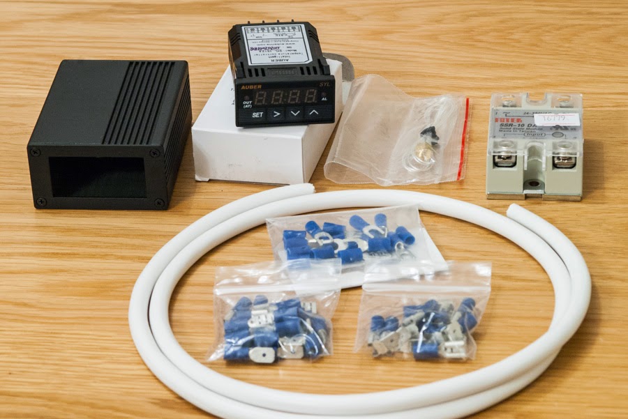
The main three components of PID kit is PID controller itself, temperature sensor and Solid State Relay (SSR). The PID and temperature sensor I ordered directly on Auber Instruments website. These guys are actually developing them, not just replicating, like those who sell its cheap clones on eBay. The PID model is SYL-1512A, this is a universal controller in compact 1/32 DIN case. The manual is easy to understand - device is pre-set for being used with SSR, so all you need to do after installation is to configure it to use RTD sensor, set the desired display unit, set the temperature to 105-106 C and run automatic calibration. I have also ordered a matching case to make it look more professional. It is high quality aluminium powder-coated case comes with front panel and also has a hole for cable on the back side.

The temperature sensor I have ordered was PT100M4, this is high-accuracy platinum RTD sensor with M4 threading on the probe and 45cm Teflon-coated cable (the left one on the picture below). It is ready to be used instead of original bi-metal one (the right one on the picture), no modification is required.

Solid State Relay (SSR) I have ordered from eBay. It is 10A SRR which is far above the current used in coffee machine, making its usage safe. The role of SSR is to control boiler high voltage power circuit by low voltage signal triggered by PID. In addition to that, I have bought a number of other items like connectors, terminals to make modification look better and less invasive. You can access the full Bill of Materials here. In total I spent £75 including postage. The only thing I did not buy was the power cable which I already had. Notice, that Auber Instruments also offer Coffee Machine Kits. This is basically the full kit to add PID to your coffee machine including all required components. It might be a good option for someone who does not want to mess with soldering, terminals, cables, etc. for me it was more interesting to spend some time and complete my DIY project.
Circuit diagram
Before putting everything together, I would like to make clear what actually is going to be achieved. Here you can download an original circuit diagram for Gaggia Classic. I sketched its copy for demonstration purposes.
Recall what PID is doing: it continuously monitors the temperature of the boiler using high-accuracy RTD temperature sensor and controlling heating element power circuit much more granular and precise way than bi-metal thermostat. Thus, PID device should be playing the role of existing bi-metal coffee thermostat ST1. To achieve that, coffee thermostat ST1 needs to be replaced with RTD temperature sensor, which will be used by PID for temperature readings to control heating element power circuit of coffee machine (previously controlled by ST1) using SSR. In addition to that, PID controller needs to be powered up when coffee machine is turned on. The modified diagram is shown below:

Putting everything together
First step was to prepare cables. I used a couple of cables to connect SSR to heating element circuit. It was 2 mm cable suitable for 10A current, similar to one used in the coffee machine already. I used spade terminal on one end to connect to coffee machine circuit and spade-tongue terminal on the other end to connect to SSR.
Another cable was used to connect SSR to PID. SSR is triggered by low voltage (8V), so cable used was relatively thin. Again, spade-tongue terminal on one end for SSR connection.

Both cables were connected to SSR terminals.

Cables to power up PID were needed as well. I used three cables, but in fact PID manufacturer claims that earth is not needed since the case and controls are made of plastic. The power consumption of PID is less than 2 W, so I used thinner cables here, about 1 mm in diameter. As these cables are connected to terminals that are being used by existing circuits, so piggy back terminals were used on these cables.

Cables preparation is completed. Now let's move to assembling steps.
If you are using my steps as a guide, make sure that coffee machine is not powered before doing anything to it, remove power cable from the connector on the back of machine to be completely sure.
Next thing I did is fixing SSR to the back wall of coffee machine. I used one M4 screw with a washer to do that.

As per diagram mentioned earlier, I detached cables from bi-metal coffee thermostat (at the bottom of the boiler) and connected them directly to cables attached to AC terminals on SSR (1 and 2 on the picture above).

Using small adjustable spanner, I unscrewed and removed bi-metal coffee thermostat (shown on the right on the image below).
I applied some thermal paste to RTD sensor, before screwing it up at the former bi-metal thermostat location. Notice that I rolled up the cable into small ring to make screwing easier.

Then I sorted power cables. Neutral and Earth went directly to power connector on the back.

Live one was connected to the power switch. I used steam switch terminal as it gets powered once machine is turned on and has more space around for piggy back terminal.

The cables inside machine were organised using plastic strap and fitted through the ventilation holes outside for PID connection. I made sure that no cable is touching the boiler, as this is important. There were 7 cables that went outside: 3 for 220V AC power, 2 from SSR and 2 from RTD sensor. Notice, I have moved SSR to the left - in previous position it made difficult to fit the top cover, but since this picture was made later, you may see SSR located at previous place on some other images below.

All cables needed to be fed through the small hole in the controller case and connected to PID according to diagram.

Power cables were connected to terminals 1 (Live), 2 (Neutral) and 3 (Earth).

SSR cable was connected to SSR output (terminals 9 and 10). RTD sensor was connected to sensor input (terminals 7 and 8, notice that 6 and 7 were also connected together using piece of wire).

Once everything was connected, I screwed the front panel and the case was assembled. I attached a piece of adhesive magnetic sheet to the case, so that it could easily be fixed to the side of coffee machine like on the picture below. Also I installed spiral cable wrap to that short outside section to make it look neater (not shown on the picture).


As I mentioned, PID configuration is fairly straightforward. For PID parameters I selected auto-tuning which set optimal PID parameters automatically.

The main advantage of PID controller is that temperature can be adjusted easily whenever needed. Notice that set temperature is above the actual water temperature in the boiler, it is roughly 10 degrees above. 105 C on the controller corresponds to 95 C brew temperature. If this is not the right one for your espresso, it can easliy be changed using up/down buttons on the PID.
Final remarks
I was inspired with PID installation after reading coffee forums and other enthusiasts websites. I particularity grateful to people from coffeegeek.com for interesting discussions, and the author of "Murph's Silvia PID Page".
A fantastic article, thanks so much. I've been enjoying my Gaggia Classic since 'getting serious' a few months ago, but have been considering a PID. There's no doubt going blind leaves me with shots that go from fantastic to 'meh'. Looking forward to installing this and getting a really good, consistent shot.
ReplyDeleteI'm like you and enjoy a bit of an electronics challenge, though I don't think I would have been able to do it without your detailed info - thanks again.
Glad you have found the article useful. Good luck with PID installation, it really makes a significant difference in shots consistency.
DeleteYou inspired me and I'm going to PID my Gaggia! I am looking for materials now but I cannot find the dimensions of thermostat/RTD sensor screw. Is that 4 or 4,5 mm in diameter? What about length? Thanks for any help :)
ReplyDeleteHello thesiu, the thread is M4 (4mm), the length is 6mm. Good luck with PIDding your Gaggia!
DeleteHello again! I have ordered PID, SSR and temperature sensor but I need to buy necessary terminals (piggy back etc). The terminals you have used are 4,8 or 6,3 mm? And what about cables... are they suitable for high temperature environment? Thanks a lot for your help :)
DeleteHello, terminals are 6.3mm, cables are normal, but thick enough. If you find temperature resistant one that will be better of course, but the temperature of the boiler when it is hot is not sufficient to melt the "normal" cable housing in fact. To be on safe side, make sure that cable does not touch boiler inside the machine (e.g. add yours to existing cable harness using plastic ties).
DeleteOne more question: what is the approximate length of cables you used? PID-SSR, SSR-heating element, PID-power. I need to prepare cables in the next few days and unfortunatelly have not access to Gaggia :/ And would a cable 0.75mm^2 10A be suitable to connect SSR-heating element?
DeleteThe easiest would be to cut cable when you have your coffee machine avialable, the thing is the one that goes from PID to front switch is longer than others, it is also good to pre-arrange them inside machine and then cut given then lengh is sufficient to reach PID terminals through PID case. I do not remember the length, sorry. Those between SSR-hating element were pretty short, about 150mm. 0.75mm^2 can be used with 1440 watt maximum, Gaggia Classic consumes 1425 watt - I think I used 1mm^2 cables for extra reliability.
DeleteHello Mr. Kabalin!
ReplyDeleteThanks for your tutorial. I started to install the pid but some quiestion arised during the process. May i ask you, that:
1) When you connect your new cables to the bimetal connector, you plugged your new brown colored cable(from ssr) to the old blue colored cable and your new blue colored cable (from ssr) to the old double, white colored cable?
/http://1.bp.blogspot.com/-63eKXw2kIGs/UacIYx-eW2I/AAAAAAAAE-4/VjakAT59zhs/s1600/IMGP8093.jpg/
2)When you connect your new cables to the power connector on the back: your new green-yellow colored cable was connected to the old green - yellow colored cable? AND your new blue colored cable was connected to the old brown(? in my machine, but not the old yellow-green colored and not the old blue colored cable but the another one on your picture)?
/http://1.bp.blogspot.com/-47agHLWQ7Ck/UacIipKQ4uI/AAAAAAAAFAA/QMiM8jkTxzE/s1600/IMGP8108.jpg/
Thank You!
Hello FA! I think the colour matching stategy is not a good one, you need to understand the scheme and what you are doing. The basic idea is to make SSR acting as former bi-metal thermostat (turn on and off the heating element), so both cables that were connected to thermostat (white on my picture) go directly to SSR terminals 1 and 2. Another thing you need to reach, is to power up PID when coffee machine is ON. Green-yellow (earth) is not needed really (as PID manual suggests), so you may omit it if you like, it is optional. You are right, I used blue cable to connect PID to brown cable (live) at the power connector side, and brown one to connect PID to blue cable (neutral) at the switch, but that is because my brown was longer than blue and it was easier to use brown to reach the switch.
DeleteBe careful with what you are doing, messing up power cables may lead to electric shock and various kind of damages, if doubt ask someone competent for help - this job is not about matching colours, you need to undestand what you are doing.
Thanks for your answer!
DeleteFirst i would like to "mimic" your job. After that i would like to check my work with the wiring diagram. Unfortunately i didnt learnt anything about electric circuits :(
The cable which i had to unattach from the bimetal termostat: how can you distinguish them? Is there a + or - on the bimetal termostat too? Or i can use any of those cables to attach my cables from ssr?
There is no + and - in alternating current and bimetal thermostat is just a "switch" that is triggered by temperature, so no need to distingush those cables.
DeleteHi again!
DeleteSorry for disturbing you, but i have some questions. I finished the wiring, but something is not OK.
I set up in the pid the sensor type to K and metric to Celsius (these were already saved values in the pid menu).
The measured value shown 28: which was a bit cold to me, but i tought it will be ok to test: i set up the setting value to 30 and wanted to see that when 30 reached, it is stop to heat the boiler.
But the behaviour is (the led in the ssr flashing, the led: "out" in the pid flashing, and the led: "temperature reached" in the gaggia classing flashing too (it sometimes give output from pid sometimes not thats why it is flashing i think) :
https://www.youtube.com/watch?v=HQCcay2ziAg&feature=youtu.be
Do you have any tips why is it happening?
When pid gets power i give the following output for some seconds (which means that sensor type set to K and metric to Celsius)
https://www.youtube.com/watch?v=A6N8XWREdAA&feature=youtu.be
accurate information about my pid's properties:
Deletehttp://www.kephost.com/image/F2Fb
and
http://www.kephost.com/image/F2Fj
Hi FA, connection to PID (your pictures) seems OK to me. The flashing behaviour is normal, it is how it should work really (assuming the boiler heating works and it is not just flashing LEDs only), it is "powering up" the boiler via PID in short intervals (you see those short intervals when LED/button is "on" and "off"), that is how it is reaching and maintaining the exact temperature. I am not sure whether your PID model has "learning" functionality, mine has a learning mode where it is estimating the time needed to reach the temperature and adjusting the heating intervals and automatically.
DeleteThanks for your answer!
DeleteSomebody told me that my pid is not ok for this project because it has "VOLTAGE" output as you can see the picture(http://www.kephost.com/image/F2Fj), not "RELAY" or "SSR" output.
What do you think about that?
You have PID model that is using 12V DC ouput to trigger SSR (I had a look at https://www.mpja.com/download/rex-c100.pdf), that is exactly what you need, assuming it matches your SSR spec requirement (my SSR was triggered by any voltage between 3 and 32 volts, as you can see on the picture).
DeleteI think my ssr should be ok: http://www.kephost.com/image/F29N
DeleteIs it?
Isn't it?*
DeleteYes, it is designd for the same range 3 - 32 V.
DeleteAnd i think as you can see the video my pid measures (pv) 30 degrees. But at that time the boiler and the water was very very hot!
DeleteHAve you any tips why is it measuring wrong value? :/
Most likely the wrong sensor settings or sensor is measuring something different than boiler :) Are you using RTD sensor or thermocouple sensor? What is the full spec? If it is not RTD, then you wired it a bit wrong. Also, what is the temperature it is showing if you turn on the cold machine?
DeleteI have a K-thermocouple. When it is turned on it showd 28 degrees. After about 5-6 mins it reached (29 and then) 30 degrees :/
DeleteRight, so you connected it wrong then, for thermocouple use only terminals 9 and 10, no neet to connect 8 (I am assuming that diagram on the sticker http://www.kephost.com/image/F2Fb is correct).
DeleteHi!
DeleteThanks for your answer and support! I connected my sensor to terminals 9 and 10 and the result is here:
https://www.youtube.com/watch?v=3yuWDzx4CFo
(there was a -- sign on the red wire, so i connected it to the - terminal ... )
after i switched terminals 9 and 10 the result much better: https://www.youtube.com/watch?v=8Lt2ELTlhmo
The pv value goes over the sv value -> that means i have to play some with the p, i, d values ? (which can be set in the pid menu?)
That temperature value seems to be ok?
The flashing of led disturbs me :/ I have got some information that the ssr needs 7.5mA current to be triggered (based on fotek 25a ssr manual) and the pid with "VOLTAGE" output (instead of relay) can not serve this and it is flashing because pid tries to trigger the ssr-> not success -> goes off->tries again->not success->go off and so on. What is your opinion about that?
ps.:(after i switched terminals 9 and 10 -> means i switched the wires not the terminals :) )
DeleteThe second video (https://www.youtube.com/watch?v=8Lt2ELTlhmo) looks like it is functioning absolutely correct. The reason PV (measured value) goes above SV (set value) it probably because control pulses are too long, so the latest pulse (that makes SSR "on") before it reached set temperature, make the boiler hotter than set temperature, then it stops pulsing (because set temperature is reached) and waiting till it goes down below set temperature, and then starts pulsing again. So, you are right, you need to adjust p, i, d values, but it seems your PID can do that for you (see auto-tuning mode in the manual https://www.mpja.com/download/rex-c100.pdf). Before starting autotuning, make sure that boiler is hot (reached the set temperature), and do not start shot pulling during autotuning, just wait till it completed and check that p i d values have been updated.
DeleteDo not worry about flashing LED, it is barely an indicator that SSR is triggered (powered on by PID), it is not that smart to indicate about failures :)). If SSR did not work, the boiler would not getting hot. My SSR is doing the same, blinking synchronously with the LED on front panel of PID.
Thank you for your help and entire support! You helped so much! Thank You!
Delete(now i just make a house for the pid because the wiring, and think about buying another rexc100 with different output just to see what that makes with my gaggia and learn from the results :) )
Thank You again!
No problem, enjoy the great coffee ;) You can try different PID of course, just keep in mind that PID with "relay" output may not work at all in same settings, because it will require external source of power to control SSR. For example, the guy on this video https://www.youtube.com/watch?v=2NpcMycHDvk is modifying "relay" version to make it work with SSR (beasically he converts rex-c100fk02-M into rex-c100fk02-V, the one you already have).
DeleteHi, me again. Question - how do you get to a temperature which you feel is correct? I set mine initially to 105 as you suggest but I have now dialled it down to 102 as I 'think' the results are better. Is there a more scientific way to confirm the best temperature? I understand that each coffee is different, but my palette isn't yet refined enough to be to judge it accurately.
ReplyDeleteGarchy, I am doing the same what you did, just adjusting depending on what I feel is better. You can do some assumptions, like darker roast require lower temperature, but that may not always lead to better taste. If all other parameters you think are correct (e.g. extraction time is right, the coffee is fresh), but you still getting bitterness, try to reduce a temperature and see how it will affect the taste, if it make things worse, bring it back to one you liked more. It is really about what you feel is better, with experience you will be able to adjust it more precisely. There are some ways to measure the exact temperature at the portafilter (it requires additional equipment), but I never bothered doing that to be honest.
DeleteDo you have any idea if this works on the SYL1512A?
ReplyDeletehttp://coffeeforums.co.uk/showthread.php?22080-Unlock-Enable-Auber-Pre-Infusion-timer-setting-on-Auber-PID&p=264179#post264179
No idea, and can't test any more (upgraded to HE machine). Hmm, I am not sure how pre-infusion should work in this scenario, PID is not controlling the pump at least in the connection schema I am aware about. My guess would be it is using PID "alarm" relay to control pump circuit when someone wants to make use of pre-infusion mode?
DeleteIt may also help others to know that I've started making pt100 sensors for the Gaggia (with 4mm threads) - like the Auber ones but better made. I did this purely to help UK owners avoid the cost and hassle of obtaining them from Auber in the US - which is the only real alternative. Simply search for my Pt100 RTD post on coffeeforums.co.uk and contact me there to buy.
ReplyDeleteFeel free to provide a direct link if you think my post will bring you some customers ;)
DeleteAs per my other post below, here's my Pt100 sensor with M4 screw:
Deletehttp://www.ebay.co.uk/itm/Pt100-RTD-temperature-sensor-for-Gaggia-and-Rancilio-PID-controllers-/121994262204
Can you please send us a link so we can find your rtd sensor?
ReplyDeleteI guess this is the question for the guy who commented above and suggested alternative model? The one used in the post has been purchased on Auber website.
DeleteSorry for the delay in replying to this... I sell them on eBay now:
Deletehttp://www.ebay.co.uk/itm/Pt100-RTD-temperature-sensor-for-Gaggia-and-Rancilio-PID-controllers-/121994262204
I also do a complete PID kit, as well as 1/32DIN and 1/16DIN aluminium enclosures for the PID controller with the cutouts already made.
Fantastic article, with crystal clear explanation and pics. I own Gaggia Classic, and found great info on the Gaggiausergroup website. Since I do not have an electrical engineering background, I have ordered from Auber the complete kit (which has arrived through FedEx this morning), now all I need to do is install. It is surprising to find that Gaggia is choosing the cheap option for controlling the temperature (obviously all related to the price), but I wish they would at least offer the Gaggia with PID as option.
ReplyDeleteGaggia is consumer coffee machine, I would not expect much in terms of precision and features (I guess you have adjusted pressure to 9 bar, because default one is 12 bar for marketing reasons). Good thing it has good build quality that makes possible to do some modifications.
DeleteGaggia is consumer coffee machine, I would not expect much in terms of precision and features (I guess you have adjusted pressure to 9 bar, because default one is 12 bar for marketing reasons). Good thing it has good build quality that makes possible to do some modifications.
DeleteYes, Gaggia is consumer coffee machine and in terms of quality is reasonably built I would say. And yes have adjusted the pressure to 9 bar.
DeleteWell, before and after (installing PID)! Have to say it makes a huge difference for me. As you mentioned in this Blog "it is all about the temperature", and I can't agree more. I would highly recommend to install.
DeleteGreat write up! Is your Gaggia 220V? Can this be applied to the Gaggia Evolution? Any difference for using US 120V vs. your 220V configuration?
ReplyDeleteFrom technical point, there is no configuration difference as long as SSD and PID can work with 120V (models as in this description both able to use 120V). But I have no idea if this can be applied to Gaggia Evolution as it may have a different wiring and controls.
DeleteGood to know. I'll probably end up with a Classic eventually - the Evolution is incredible, but it lacks the 3-way valve - so I'm usually left with a sloppy mess of water if I use fresh grounds. I primarily use it with espresso pods (which are pretty dang good actually!), so the valve isn't necessary - but the right temp. for brewing is always nice!
DeleteThanks for the reply!
Why have you not bypassed the steam thermostat as well? Is the idea just that the steam temperature control is good enough and you don't want to deal with having to readjust the PID for steam each time?
ReplyDeleteThat's what I'm thinking - steam just needs to be hot enough for...steam! Why bother play with it if it's working? It's the brewing temp for extracting flavor from espresso that is usually not hot enough.
DeleteSteam does not require that precise temperature control, original bi-metal steam thermostat does it job perfectly, so there is no need to modify anything in my opinion. However, there are examples on the internet that implement steam control using PID as well, the main purpose to increase temperature a bit (within a safe range) to achieve higher steam pressure. One of the ideas to control steam temperature is using "alarm" setting in PID (it allows you to set a separate alarm temperature that trigger connection between two other terminals on the PID), in which case you won't need to modify PID settings each time you steam. Obviously circuit diagram modification is required if you want to use that feature.
DeleteJust the great write-up, but a brown cable hooked up to the steam switch terminal (the second one in the first row) is kind of misleading, since all "L" connections are blue in Gaggia Classic wiring.
ReplyDeleteThanks Yuri! Yep, the colour is somewhat misleading indeed.
DeleteHello Kabalin
ReplyDeleteThanks for your tutorial, one question.
(you sorted power cables. Neutral and Earth went directly to power connector on the back)
(Live one was connected to the power switch).
What about if I put them all to the power connector on the back (Neutral + Live)? Is it OK?
Best Regards.
Hello Abdullah, hope you found the tutorial useful. You can connect PID directly to power connector, but PID will be constantly turned on (unless you unplug coffee machine from the wall socket).
DeleteHello.
ReplyDeleteThank you very much for this article. Could you please tell me will this work for GranGaggia (RI8323/08)? I want to upgrade mine also.
Fantastic article, many thanks! Just completed the installation. One thing worth noting -- mine came from Auberins with a Sv temp of 800F, so I almost burned out my heating elements before I figured it out! My first thought was that the sensor was broken -- checked all wiring etc then realized what was probably the issue. After that, auto learning and all went well. Thanks again.
ReplyDeleteHi Ruslan,
ReplyDeleteNot sure if you are still monitoring this, but if so I have a question. I followed your guide with a few adjustments to accommodate my version of the Gaggia (e.g. I have no ground terminal). The only issue I have is my Steam button no longer does anything. I click it on and open the steam knob and nothing happens.
I have the live power for the PID connected to the Steam power line. Removing this and simply plugging the Steam power back on did not change anything. If you need more info I can take some pictures when I get home to show you my wiring.
Thanks for the great guide!
FYI Turns out I had changed out the wrong thermostat. The boiler one is down on the side, and I had removed the steam one by accident, which is the one on top with the red dot.
DeleteExcellent article, if you take your coffee serious, you really need to install this, it's costing peanuts and your coffee doors just improve so much. Installation is a breeze as long as you follow the instructions to the TV.
ReplyDeleteMany thanks for excellent photos and explanations - something I want to after I combined two machines into one to make a twin boiler machine. Nice to see a simple version as some PID solutions as overly complex for controlling heat.
ReplyDeletehttps://www.reddit.com/r/Coffee/comments/9s05lb/blogs_and_videos_i_used_to_add_a_pid_to_my_gaggia/
ReplyDeleteI relied heavily on your blog to add a PID to my Gaggia classic. Your blog was great, but I needed a bit more information about wiring and programming my PID from a youtube channel. I owe you a big thanks.
Great write-up Ruslan..I used your suggested pid,and thermo..adjusted to pt100,celcious,105c..then did autoset after boiler warm up...how long does the auto program take to finish?..mine seems to run forever..thanks Charlie..120v gaggia classic
ReplyDeleteHi, can you please tell me what PID values you have settled on? Using auto tune on Auber SYL 1512AR provides different values depending when I activate it. I’m interested to see what others have these values set also. Auber recommends 2, 60, 15 for pid but after auto tune it’s different
ReplyDeleteI've actually been struggling with this a bit myself. I still am getting a big temp drop (10 degrees) during a 25 sec extraction. So clearly my numbers are no good. Would love to hear from folks what they are using and how much temp consistency they are achieving.
Deletethanks for sharing such an informative post.
ReplyDeleteFound your guide quite helpful. Initially I wanted a second SSR for steam but could not get it to work so I just went with your guide. https://imgur.com/a/mJgHqiO Do you think it is best to run the auto-tune as soon as you turn it on or after the temp has stabilised after 10-15 mins? I ended up using the XMT7100 PID which is either a clone or rebadged Auber as it has the same pin outs. I've found opening the steam at 135-140c allows for perfect steam so I don't really think the steam SSR is needed.
ReplyDelete
ReplyDeleteIf there is some kind of award or reward for great content, this material should win it. I have not read such good quality content in a while. Thank you.
I don't normally comment on articles, but I have to on this one. Your article is very well-written with a lot of useful, original and bold views on this topic. For more than 20 years, Ulka Pumps has been providing quality solenoid pumps, solenoid valves, and industrial products with outstanding reliability for a variety of different applications. Our products are manufactured proudly in Italy, built to the highest standards to meet the expectations of all our clients.
ReplyDeleteYour article is an excellent showing of writing skills that my children should be using. You have captured readers with your compelling and interesting views. Quality product manufactured in Italy Ulka EAP5 Power: 120V / 60Hz / 52 watts NSF Certified Plastic Outlet.
ReplyDeleteI agree with many others that this is the best DIY PID guide for the older (Pre-2015?) Gaggia Classic machines that I've read so far. Much gratitude to RK!!!
ReplyDeleteThis comment has been removed by the author.
ReplyDeleteCable lugs are a great way to ensure strong, secure connections, especially when you want your setup to stay reliable over time.
ReplyDeleteDiscover the complete 7 Brew Coffee menu for 2026, featuring the latest drinks, prices, calories, and customization options—all in one place. Whether you’re craving classic espresso drinks, refreshing iced coffees, energizing blends, teas, or creamy shakes, this guide helps you explore every option before visiting your nearest 7 Brew drive-thru.
ReplyDeleteClassic Coffee
Great article! I really appreciate the level of detail you shared throughout this PID installation project. The explanation of temperature stability and the step-by-step approach make it much easier for readers to understand the benefits of precise control and quality components. At Vanel Tech, we value engineering-focused solutions and technical innovation, so this was a very interesting read. Thanks for sharing your experience and insights!
ReplyDelete